This is my play by play through his example 2, where he pulls in an axi_gpio block.
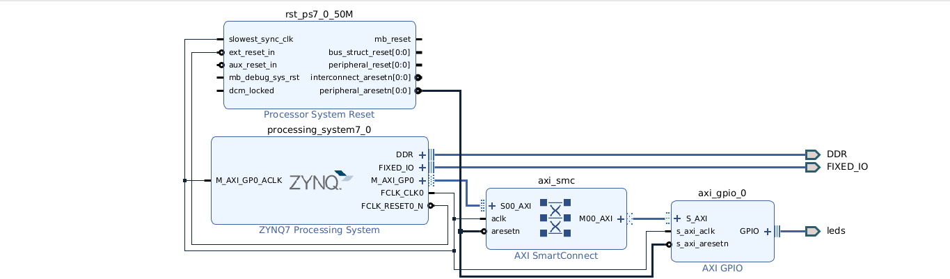
The Vivado veteran will look at the above diagram and spot something new and different. I am using Vivado 2024.2 and this generates the axi_smc block. Prior versions of Vivado would have an axi_interconnect block.
We launch the vivado GUI again. We create a new project s9_blink_example2, this time taking care that it goes into the /home/tom/vivado directory. I call the block design "gpio". We add the Zynq block and run block automation, which connects DDR and FIXED_IO. I leave the fabric clock at the default 50 Hz.
I add the AXI GPIO block. I configure the width to 4 (rather than 8) since I have four on-board LED. We run connection automation, and select both GPIO and AXI (just select "all" automation). This creates a port gpio_rtl_0, but we can rename it to "leds". Bring up a menu, select "external interface properties" and change the name to "leds", be sure and hit return and look at the block diagram to be sure the name changes. The Tcl so far is:
create_bd_design "gpio"
Wrote  :
update_compile_order -fileset sources_1
startgroup
create_bd_cell -type ip -vlnv xilinx.com:ip:processing_system7:5.5 processing_system7_0
endgroup
apply_bd_automation -rule xilinx.com:bd_rule:processing_system7 -config {make_external "FIXED_IO, DDR" Master "Disable" Slave "Disable" }  [get_bd_cells processing_system7_0]
startgroup
create_bd_cell -type ip -vlnv xilinx.com:ip:axi_gpio:2.0 axi_gpio_0
endgroup
set_property CONFIG.C_GPIO_WIDTH {4} [get_bd_cells axi_gpio_0]
startgroup
apply_bd_automation -rule xilinx.com:bd_rule:board -config { Manual_Source {Auto}}  [get_bd_intf_pins axi_gpio_0/GPIO]
apply_bd_automation -rule xilinx.com:bd_rule:axi4 -config { Clk_master {Auto} Clk_slave {Auto} Clk_xbar {Auto} Master {/processing_system7_0/M_AXI_GP0} Slave {/axi_gpio_0/S_AXI} ddr_seg {Auto} intc_ip {New AXI SmartConnect} master_apm {0}}  [get_bd_intf_pins axi_gpio_0/S_AXI]
Slave segment '/axi_gpio_0/S_AXI/Reg' is being assigned into address space '/processing_system7_0/Data' at <0x4120_0000 [ 64K ]>.
endgroup
regenerate_bd_layout
set_property name leds [get_bd_intf_ports gpio_rtl_0]
I left in one important output "comment" because it shows the address assigned to the GPIO.
He points out something important. We can change this address using the address editor.
Just to see the Tcl that might be used, I do this, changing it to 0x4100_0000.
He says that we could trim the address range back to only 512 bytes, but we go ahead
and use the full 64K as per the default.
set_property offset 0x41000000 [get_bd_addr_segs {processing_system7_0/Data/SEG_axi_gpio_0_Reg}]
We create the HDL wrapper, giving us:
make_wrapper -files [get_files /u1/home/tom/vivado/s9_blink_example2/s9_blink_example2.srcs/sources_1/bd/gpio/gpio.bd] -top
add_files -norecurse /u1/home/tom/vivado/s9_blink_example2/s9_blink_example2.gen/sources_1/bd/gpio/hdl/gpio_wrapper.v
set_property IOSTANDARD LVCMOS33 [get_ports {leds_tri_o[*]}]
set_property SLEW SLOW [get_ports {leds_tri_o[*]}]
set_property DRIVE 8 [get_ports {leds_tri_o[*]}]

set_property PACKAGE_PIN F16 [get_ports {leds_tri_o[0]}]
set_property PACKAGE_PIN L19 [get_ports {leds_tri_o[1]}]
set_property PACKAGE_PIN M19 [get_ports {leds_tri_o[2]}]
set_property PACKAGE_PIN M17 [get_ports {leds_tri_o[3]}]
Go to sources, click the "+", tell it to add constraints, create the (empty) leds.xdc file.
Finish. Then find and open the file. On my system this launches vim and I copy in the
above stuff.
The "tri" naming business is because the leds port is an interface port with multiple (3) signals. The _o is selecting the output signal since that is what we asked for.
Again, we use the dandy shortcut of clicking "generate bitstream" at the lower left. This will take several minutes and we wait for the popup to let us know it is done.
inout [3:0]leds_tri_io;When I created the AXI GPIO block, I should have clicked the checkbox "all outputs".
startgroup
set_property CONFIG.C_ALL_OUTPUTS {1} [get_bd_cells axi_gpio_0]
endgroup
Now I click on "generate bitstream", which reruns synthesis and implementation.
It works now. I peek at gpio_wrapper.v and see that we now have:
output [3:0]leds_tri_o;The bitstream is now:
/home/tom/vivado/s9_blink_example2/s9_blink_example2.runs/impl_1/
I am using my Kyu RTOS for code on the ARM. I need to add a GPIO driver for the AXI gpio that we just created, and be sure that is has the proper base address. I have one in my ebaz bare metal demos. I copy it into Kyu, make a few edits, change the base address and compile it all.
It works! I am writing 0x5 then 0xa to get a back and forth pattern on the four LED>
Timing is set by the 1000 Hz timer in Kyu.
Tom's Computer Info / tom@mmto.org