In its barest state, a custom AXI peripheral is a group of registers that can be accessed from the PS. Unlike the AXI_GPIO, these registers don't conform to any protocol and need to be customized. This is done by editing the verilog templates that vivado generates and perhaps adding additional verilog files.
We launch vivado and let the new project wizard guide us.
We need to remember our part number as we are eschewing specifying
the board. It is xc7z010-1clg400.
Nothing special here and the Tcl is:
create_project custom1 /u1/home/tom/vivado/custom1 -part xc7z010clg400-1
set_property  ip_repo_paths  /u1/home/tom/vivado/ip_repo [current_project]
update_ip_catalog
Now we use Tools on the top menu and select "create and package new IP". We want a new AXI4 peripheral. I call it "fancyled". I will use AXI4 Lite and I want 8 registers, not 4. I tell it to "add IP to the repository".
create_peripheral user.org user fancyled 1.0 -dir /u1/home/tom/vivado/ip_repo
add_peripheral_interface S00_AXI -interface_mode slave -axi_type lite [ipx::find_open_core user.org:user:fancyled:1.0]
set_property VALUE 8 [ipx::get_bus_parameters WIZ_NUM_REG -of_objects [ipx::get_bus_interfaces S00_AXI -of_objects [ipx::find_open_core user.org:user:fancyled:1.0]]]
generate_peripheral -driver -bfm_example_design -debug_hw_example_design [ipx::find_open_core user.org:user:fancyled:1.0]
write_peripheral [ipx::find_open_core user.org:user:fancyled:1.0]
set_property  ip_repo_paths  {/u1/home/tom/vivado/ip_repo/fancyled_1_0 /u1/home/tom/vivado/ip_repo} [current_project]
update_ip_catalog -rebuild
Now lets create a block design and add this to it. We go with the default "design_1" for the name.
I use the big "+" to add IP and I find "fancyled" among the options.
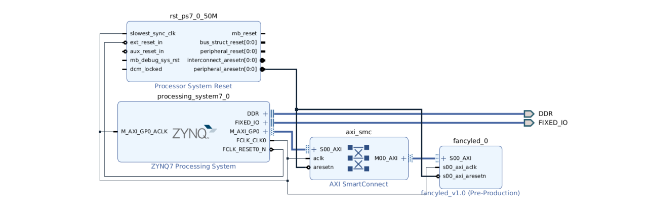
create_bd_design "design_1"
update_compile_order -fileset sources_1
startgroup
create_bd_cell -type ip -vlnv user.org:user:fancyled:1.0 fancyled_0
endgroup
Now let's add the Zynq block and run both block automation and connection automation. This pulls in the "rst_ps7_0_50M" reset block and an "axi_smc" block. It also makes connections to the (useless) DDR and FIXED_IO.
startgroup
create_bd_cell -type ip -vlnv xilinx.com:ip:processing_system7:5.5 processing_system7_0
endgroup
apply_bd_automation -rule xilinx.com:bd_rule:axi4 -config { Clk_master {Auto} Clk_slave {Auto} Clk_xbar {Auto} Master {/processing_system7_0/M_AXI_GP0} Slave {/fancyled_0/S00_AXI} ddr_seg {Auto} intc_ip {New AXI SmartConnect} master_apm {0}}  [get_bd_intf_pins fancyled_0/S00_AXI]
--- Slave segment '/fancyled_0/S00_AXI/S00_AXI_reg' is being assigned into address space '/processing_system7_0/Data' at <0x43C0_0000 [ 64K ]>.
apply_bd_automation -rule xilinx.com:bd_rule:processing_system7 -config {make_external "FIXED_IO, DDR" Master "Disable" Slave "Disable" }  [get_bd_cells processing_system7_0]
regenerate_bd_layout
In the above, I retain the "comment" that shows where our AXI peripheral has been placed in the address space.
Notice however that our custom AXI block is not part of our project. The files reside in the ip_repo area. This is perhaps good for code reuse. However, one of my goals is to be able to package up all the files for a project without dependencies and be able to put all the files on Github.
As an experiment, I create and package another IP, taking all the defaults and watching closely to see
if there is an option to just include it in the current project. There does not seem to be.
I see this as it creates the IP:
create_peripheral user.org user myip 1.0 -dir /u1/home/tom/vivado/ip_repo
add_peripheral_interface S00_AXI -interface_mode slave -axi_type lite [ipx::find_open_core user.org:user:myip:1.0]
generate_peripheral -driver -bfm_example_design -debug_hw_example_design [ipx::find_open_core user.org:user:myip:1.0]
write_peripheral [ipx::find_open_core user.org:user:myip:1.0]
set_property  ip_repo_paths  {/u1/home/tom/vivado/ip_repo/myip_1_0 /u1/home/tom/vivado/ip_repo/fancyled_1_0 /u1/home/tom/vivado/ip_repo} [current_project]
update_ip_catalog -rebuild
ipx::edit_ip_in_project -upgrade true -name edit_myip_v1_0 -directory /u1/home/tom/vivado/ip_repo /u1/home/tom/vivado/ip_repo/myip_1_0/component.xml
I see no hints here for what I would like to do.
pwd
/home/tom/vivado/ip_repo/fancyled_1_0/hdl
ls -l
-rw-r--r-- 1 tom tom 18524 Dec 19 12:12 fancyled_slave_lite_v1_0_S00_AXI.v
-rw-r--r-- 1 tom tom  2233 Dec 19 12:12 fancyled.v
I was going to add an input port "clock" to bring in FCLK_CLK0 (which is a 50 Mhz clock), but it is already available as "s00_axi_aclk". And it gets passed to the inner module as S_AXI_ACLK. Lots of stuff in the inner module gets triggered via:
always @(posedge S_AXI_ACLK)I do what I have done several times before, namely make register 0 a read only register that returns an ID code. I will use 32'habcd0012, so I do this on reset:
slv_reg0 <= 32'habcd0012;I also add "code" to accumulate a count at 1 Hz in slv_reg1.
I get errors when I simply try to write values into slv_reg1 and slv_reg2 saying that these nets have multiple drivers. What might work is to comment these out:
		slv_reg0 <= slv_reg0;
        // slv_reg1 <= slv_reg1;
        // slv_reg2 <= slv_reg2;
        slv_reg3 <= slv_reg3;
No. That doesn't do it. The message is:
Multiple Driver Nets .... slv_reg2[0] has multiple drivers (31 more like this)I tried several other things, but still get the error. I ran into this in a prior project. The solution then was only to set the slv_reg* value immediately before the value was read. Vivado 2024 generates a tangle of ternary if statements to handle the register reads, whereas Vivado 2022 used a case statment. But that really doesn't matter. What I did successfully in another project where I was letting reg3 be reg1+reg2 was to update reg3 whenever I handled the write for reg1 or reg2.
What I need to do is to look at some other peoples examples and see how they handle returning values in these registers.
always @( posedge S_AXI_ACLK )
	begin
	  if ( S_AXI_ARESETN == 1'b0 )
	  begin
		slv_reg1 <= 0;
	  end
	  else
	  begin
	    slv_reg1 <= switches;
	  end
    end
We edit in changes as per his example and try again.
I can read my counters in reg2 and reg3 just fine now though, which is nice.
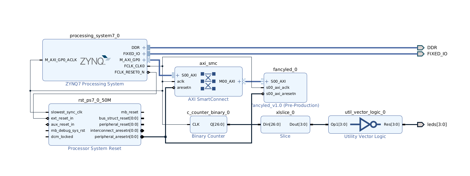
There is a block "utility vector logic". It can be invert, and, or, xor. I make it a 4 bit wide inverter, patch it in, and generate the bitstream.
<spirit:port>
        <spirit:name>leds</spirit:name>
        <spirit:wire>
          <spirit:direction>out</spirit:direction>
          <spirit:wireTypeDefs>
            <spirit:wireTypeDef>
              <spirit:typeName>wire</spirit:typeName>
              <spirit:viewNameRef>xilinx_verilogsynthesis</spirit:viewNameRef>
              <spirit:viewNameRef>xilinx_verilogbehavioralsimulation</spirit:viewNameRef>
            </spirit:wireTypeDef>
          </spirit:wireTypeDefs>
        </spirit:wire>
</spirit:port>
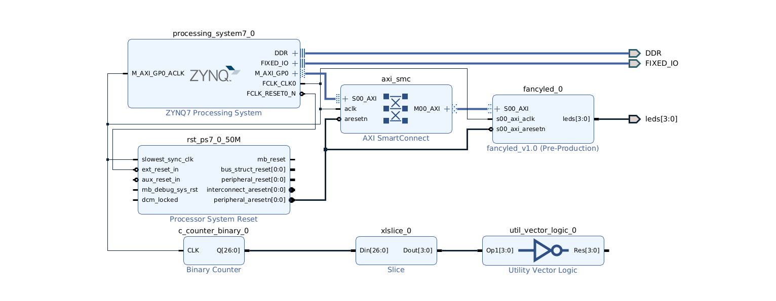
Once I do this and go through the rigamarole to update the IP catalog, an "leds" port appears on my
block diagram. Hurrah! We connect this to the external "leds" port, now leaving the vector
logic block output unconnected, and we generate the bitstream, which works!
And now we test it. It sort of works. We get only one of the four LED blinking. There must be some way to indicate that the port has 4 signals.
Indeed, I look at some of the port declarations for some of the AXI bug signals and discover that this is the trick. Add this just after the "direction" entry above:
<spirit:vector>
            <spirit:left spirit:format="long">3</spirit:left>
            <spirit:right spirit:format="long">0</spirit:right>
</spirit:vector>
I made these edits, save the modified XML, then in vivado:
A quick note about something that would be obvious to the Verilog veteran. To place a value on leds in my verilog, I do this:
output wire [3:0] leds,
reg [31:0]    slv_reg1;
assign leds = slv_reg1;
Here we are assigning from a 32 bit register to a 4 bit vector. Verilog doesn't mind this construct at all, and it uses the low 4 bits of the 32 bit register to drive "leds", so in my C code I can do this to turn off all four LED:
ap->reg1 = 0xf;The next thing I want to investigate are the issues with adding extra verilog files to my Custom IP. Can I just add a file, or will modifications to component.xml be required?
I add the following line to the start of fancyled_slave_lite_v1_0_S00_AXI.v.
`include "extra.v"Note the "backtick" at the start of `include. Yes, this is a backtick, not a single quote.
It fails with the error "cannot open include file "extra.v". Maybe there is some kind of search path issue. For whatever reason it cannot find this file in the same directory as the file including it.
This works!!
I hate it that clicking "OK" when bitstream generation finishes, launches into
"view generated design", which just wastes my time. I interrupt with Ctrl-C,
but this turns out to be a bad idea (see below).
For the heck of it, I find the string "Pre-Production" and change it to "Professional". This does not work. It needs to be one of some enumeration that I know nothing about. A bit of searching tells me that "Production" is a recommended alternative.
However this has led to all kinds of hell. It is now telling me that fancyled is "Locked by user". I revert to Pre-Production and roll up my sleeves. It is still in a snit. I exit vivado and restart. This seemed fix things. The problem seemed to start when I tried to interrupt the "view design". Clearly it is best to let things run their course, even if wrong and unwanted.
The bitstream generation finishes, but I am again bitten by clicking OK.
... sigh
I am happy that now when I edit extra.v (external to vivado using vim), vivado recognizes the file change when I save from vim and tells me that the model is out of date, so I can run through the update rigamarole.
Tom's Computer Info / tom@mmto.org