The Antminer S9 has nine of these 18 pin connectors. Each one of these has 6 FPGA pins assigned to it. This makes 6*9 = 54 signals. So what we could do is just continue our 4 pin business for the LED to include these 54 signals. We have 54 signals plus 4 LED for a total of 58 signals. EMIO allows for 64 outputs, so this all fits -- we can configure 58 emio signals in the Zynq block, make an IO port to extend all of those and then make the proper 58 entries in a constraint file and there we go.
These would all be output pins. Dealing with input EMIO is something that I have not yet figured out. We have a single regular MIO pin in each connector, and those could be either input or output. So we could have 9 inputs and 54 outputs with very little extra work. This would be a useful bitmap to generate and have on hand.
The input pins are not as hard to find as I thought. I do what I have done before, double click the Zynq block, disable the AXI GPIO that shows up by default (and requires a pesky clock), find EMIO and assign a width (as an experiment I assign 8 right now).
The trick comes next. AFter doing the above, the Zynq block now displays "GPIO 0 +". Click on the "+" and it turns into a "-" and 3 new things appear below it:
GPIO_I[7:0]
GPIO_O[7:0]
GPIO_T[7:0]
"I" is clearly inputs, O and T are outputs. What "T" is, is a tri-state control for "O". When these 3 signals are connected in the "usual way" to an output block, the T signal serves as an output direction, to use the input, the output must be put into tri-state mode. The above video shows this. We can create an HDL wrapper, then double click on it. I go to "design_1" under sources, use the menu to "create HDL wrapper", change the option telling it to create a file to allow user edits, and I see:
design_1_wrapper.vHoo hah! Verilog!! He gets the following in his file, but I don't. Hmmm. He is using Vivado 2016.1 What I think is that you will only get this if you create a port for the signals. That will generate the IO blocks and get you the following. Either I missed it in his video or he skipped that step.
inout [44:0]gpio_0_tri_io;In any case, he uses the same sysmbols in his constraint file for both buttons and led, i.e. for either inputs or outputs. Hmmm. This suggests that this "tri" object combines the three EMIO signals at the IO port! So I can control direction from the GPIO registers in the PS. Well, well, well -- this turns out to be nicer and easier than I thought, but I need to try it before I believe it.
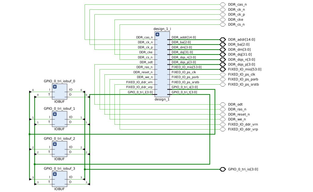
Take a look at this:
This comes from looking at the schematic under "examine synthesis" or whatever they call it. You can see the 3 signals, I, O, and T going to IO blocks that will connect to pins. This is handier than I had imagined, but you can clock on the "+" to get the individual I, O, T in the block diagram if you really want that.
Here is a hot tip (out of place, but I want to record it somewhere). All of this can be done using Tcl commands outside of Vivado. The hot tip is to do things in Vivado, but watch the Tcl console at the bottom of the Vivado screen. You will see the commands there that you can run outside of Vivado to do the things you are using Vivado to do. UG835 is also recommended. So is UG994.
Tom's Computer Info / tom@mmto.org