Somewhere I was able to buy some 2mm pitch headers and soldered one onto my "A" Antminer board. Then I did some careful soldering and actually managed to get a a connector soldered up to get my Segger clone connected. And I used this back in June to do some debugging of my "secret protocol" loader.
I just found that board and several of the carefully soldered wired have become unsoldered. So that connector will either need to be repaired or something much better put together. The following notes should be helpful:
pin 2 - 3.3 volt supply on the board
pin 4 - TMS
pin 6 - TCK
pin 8 - TDO
pin 10 - TDI
pin 12 - -- n/c
pin 14 - RST*
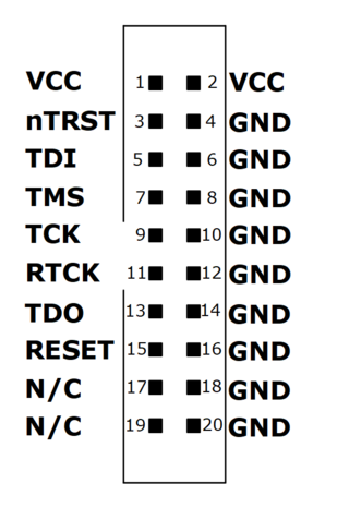
Here is what the Segger connector looks like:
The diagram is misleading in labeling both pins 1 and 2 as Vcc.
Pin 1 is the Vcc (3.3) coming from the target (Antminer).
Pin 2 could be supplying 3.3 volts to the target (Antminer),
but we have no intention of anything like that.
A meter shows that 1 and 2 are not connected.
My Segger device has grounds on all the even pins (except pin 2) as shown. Pin 2 could deliver 3.3 volts to the target, except that I have disabled this by removing a jumper on the PCB. This leaves the 10 odd pins:
Ant 2 -- Segger 1 (Vcc 3.3 from the Antminer -- check this)
Ant 4 -- Segger 7 (TMS)
Ant 6 -- Segger 9 (Tck)
Ant 8 -- Segger 13 (TDO)
Ant 10 -- Segger 5 (TDI)
Ant 14 -- Segger 3 (RST)
Ant 11 -- Segger 20 (ground)
My notes from EBAZ days tell me that the idea with Segger pin 1 (which they call VTreg) is that it "tells" the Segger what logic level your target is running on. Presumably it drives the appropriate side of some level shifters to make this work. Indeed my unit contains a pair of "245" style level shifters.
It just so happens that I ordered (from Adafruit) some 40 pin cables with 2mm female on one end in pairs and single female on the other end. I could strip off 4 of these pair (8 signals), leaving 32 for some future use. I also ordered some extra long header pins which I can use to connect those loose individual signals to the Segger cable. It will work, require no soldering, and be much more reliable than my prior solder work. In apology I should mention that the 2mm pitch female connector I soldered to was never intended to be on the end of a cable. It was designed to be soldered onto a PCB.
Ant 2  -- brown - Segger 1 (Vcc 3.3 from the Antminer -- check this)
Ant 4  -- red   - Segger 7 (TMS)
Ant 6  -- orang - Segger 9 (Tck)
Ant 8  -- yello - Segger 13 (TDO)
Ant 10 -- green - Segger 5 (TDI)
Ant 9  -- blue  - Segger 16 (ground)
Ant 14 -- purpl - Segger 3 (RST)
Ant 13 -- grey  - Segger 20 (ground)
Tom's Computer Info / tom@mmto.org