** Programming Started **
auto erase enabled
Info : device id = 0x20036410
Warn : STM32 flash size failed, probe inaccurate - assuming 128k flash
Info : flash size = 128kbytes
Error: stm32x device protected
Error: failed erasing sectors 0 to 0
** Programming Failed **
shutdown command invoked

make: *** [Makefile:43: flash] Error 1
The key line is "Error: stm32x device protected". This means that the good folks in China, when they installed the blink demo into your unit (perhaps this is something they do to test the units before shipping them), also set a security fuse.
You will have to reset this before you can use the unit, and it is somewhat of a pain.
I just went through the 22 units in my supply box, but open the static bags and tried to flash each one of them. 14 of them were protected, and 8 were ready for use.
The only way I know how to clear this is to connect a USB to serial adapter to serial port 1 and send a special command to the boot loader that is built into the chip. This command will clear the read/write protection and also erase the flash. A package deal.
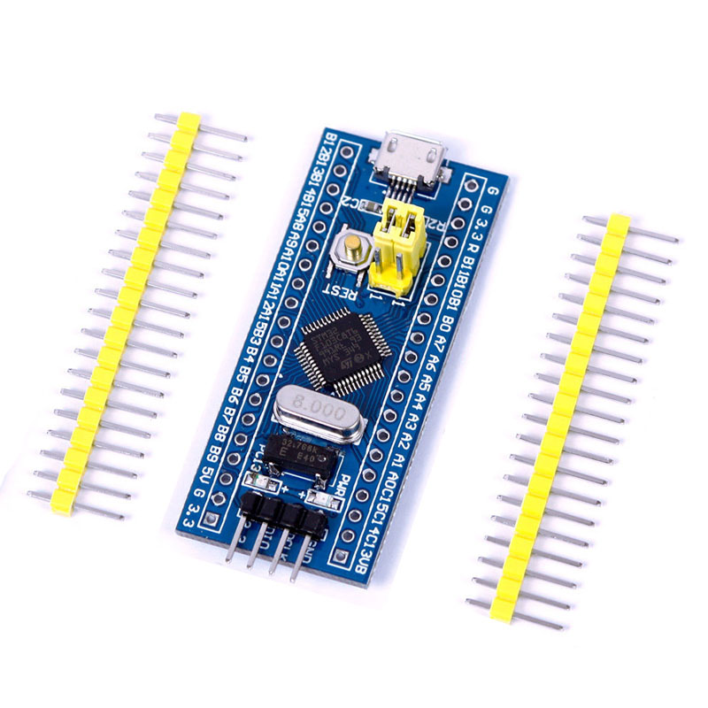
The STM32 has 3 serial ports (1,2, and 3). We want to talk to serial port 1 by way of pins PA9 (tx1) and PA10 (rx1). The signals are at 3.3 volt levels, so be sure your USB to serial gadget is talking 3.3 volts.
So grab yourself a CP2102 USB to serial gadget. Figure out some way to connect Tx on the CP2102 to PA9 on the STM32 and to connect Rx on the CP2102 to PA10 on the STM32. I know that sounds backwards, but apparenly my CP2102 was labeled backwards, or something. I power my STM32 from one USB cable, and connect another to my CP2102. Given these both come from the same computer, I don't worry about tying ground on the CP2102 to the STM32, but you should at least think about this.
Next you will need my "loader" utility from my Github:
git clone https://github.com/trebisky/stm32f103.gitThen build the "loader", which is actually a special purpose tool for doing exactly what we want to do (clear the protection on an STM32).
cd stm32f103/loader
make
Put the BOOT0 jumper on position 1 to run the boot loader in the STM32.
./loader
Timeout initializing communication with bootloader
Be sure the BOOT0 jumper is set to 1
Press RESET on the target and try again

./loader
Boot loader version: 2.2
Chip = 0410
The second is what you want to see and indicates success.
Since I have 14 units to do, and because I had some pogo pins on hand, I simply soldered two pogo pins to the Rx and Tx on the CP2102 and that made a handy gadget to process all 14 of my units. This allowed me to set up a "production line" and get all of these units prepped and ready for use without hassle.
Tom's Computer Info / tom@mmto.org