September 12, 2017
Or in case you like it better, here is another diagram:
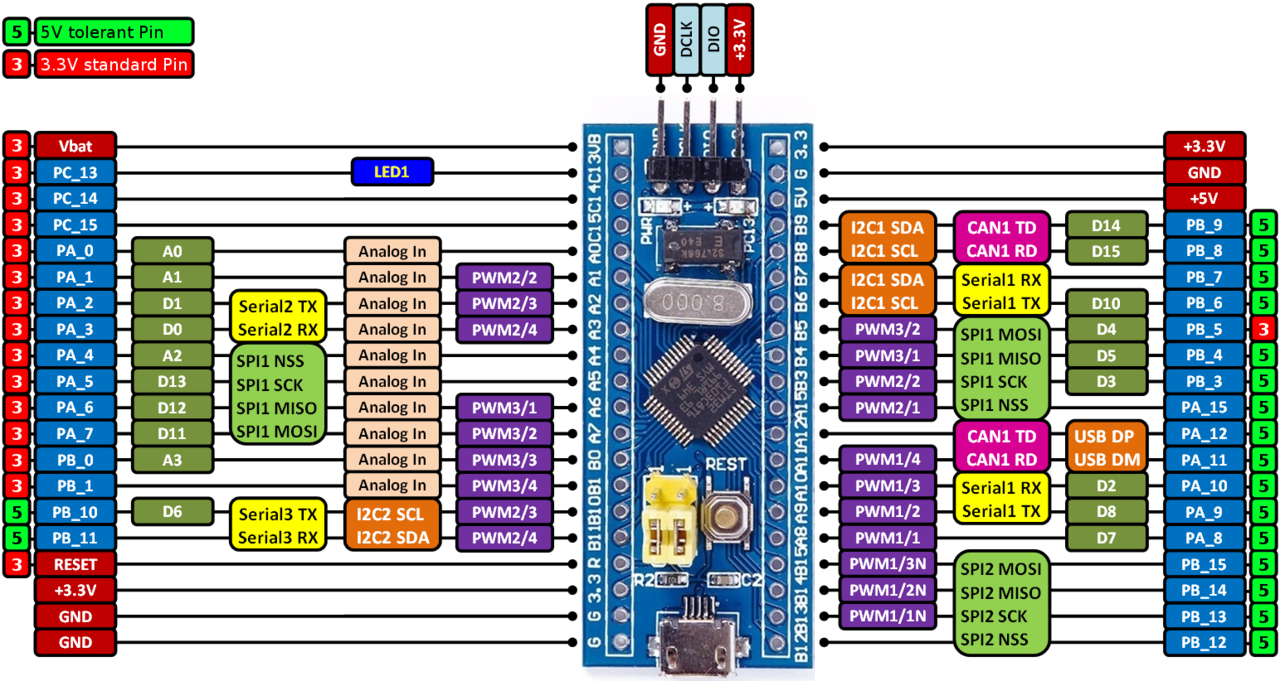
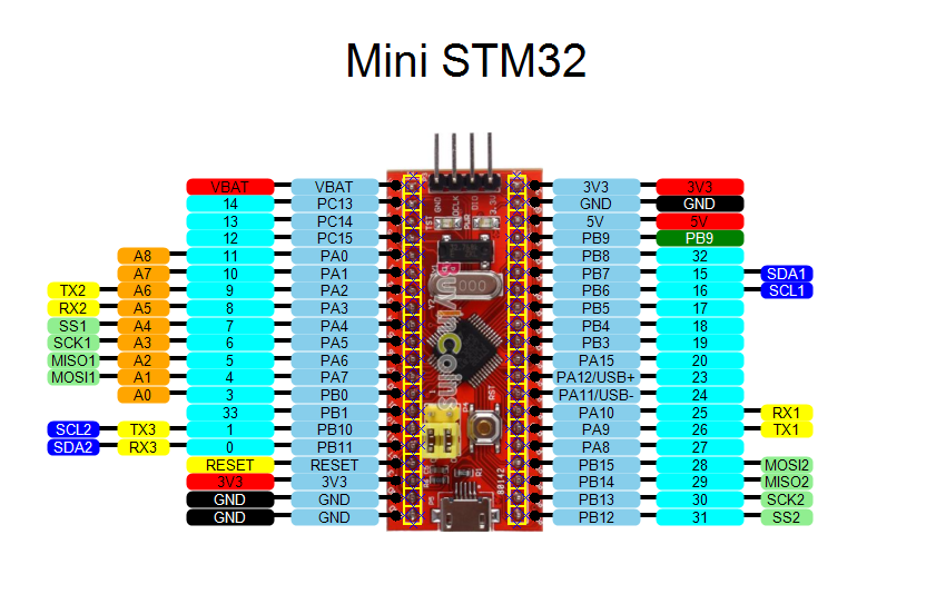
By my count, there are 30 GPIO pins you are free to use. 32 if you avoid using USB. But you say, "hey, there are three 16 bit GPIO gadgets, that should be 48 pins!". Well, a bunch (PC0 to PC12) just never made it to the outside world in the 48 pin package chip used on this board. That gets the count down to 35.
To get the count down to 30 from 35, consider these 5 pins that have been dedicated to special uses on the PCB:
PA13 is SWDIO
PA14 is SWCLK
PB2 is BOOT1
PA11 is USB
PA12 is USB
The pins along the sides are as follows. I ran an experiment outputing a waveform on all GPIO pins and note those that had issues.
Gnd
Gnd
3.3
Reset
B11
B10
B1
B0
A7
A6
A5
A4
A3
A2
A1
A0
C15 -- cannot use, crystal on board
C14 -- cannot use, crystal on board
C13 -- on board LED
V-battery (goes to the chip, see data sheet)
B12
B13
B14
B15
A8
A9  -- Uart 0 Tx
A10 -- Uart 0 Rx
A11 -- USB D+
A12 -- USB D-
A15 -- used for JTAG, see below
B3 -- used for JTAG, see below
B4 -- used for JTAG, see below
B5
B6
B7
B8
B9
5 volt
Gnd
3.3
I found the answer in RM0008, section 9.3.5. After reset these GPIOs default to being part of the JTAG interface. Table 37 shows the value to write to the SWJ_CFG field of the AFIO_MAPR register in section 9.4.2 to fix the issue. But first you must enable the AFIOEN bit in the RCC_APB2ENR register. I’ve only tested this for output but it works.
Tom's Computer Info / tom@mmto.org