July 2, 2017

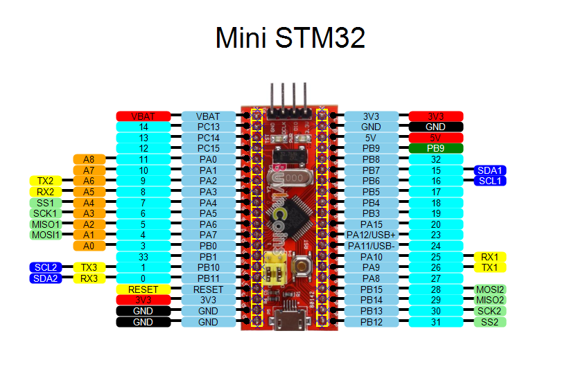
The PC13 led is controlled by GPIO C bit 13.
The PWR led is driven from the 3.3 volt power rail.
The most obvious feature when you look at one of these boards are the two yellow jumpers that almost dominate the board. These are BOOT0 and BOOT1.
These yellow jumpers are connected to the processor BOOT0 and BOOT1 lines. They can be set to connect these either to ground (in the 0 position) or to a pullup to 3.3 volts (in the 1 position).
The jumper farthest away from the reset switch is BOOT0.
There are 3 possible configurations:
BOOT0 = 0, BOOT1 = any - boot program from flash memory (normal operation)
BOOT0 = 1, BOOT1 = 0 - boot from system memory (run bootloader)
BOOT0 = 1, BOOT1 = 1 - boot from SRAM (how do we get a program there?)
The normal situation is the leave both in the zero setting. This is where I always leave these jumpers.
I never boot from SRAM (and am not entirely sure how this would be useful, maybe you could use OpenOCD to put code in SRAM and then do a reset to run it, saving wear and tear on the flash. Sounds good in theory (sort of), but nobody ever does this.
The option to run the bootloader runs the serial bootloader that uses serial port 1 (on PA9, PA10), not any kind of USB loader. So for a person like me who uses OpenOCD and the SWD port to put code in flash, this serves no purpose.
Tom's Computer Info / tom@mmto.org