When I first started working with the Pico, I just grabbed a USB cable and plugged it in. This certainly works. You can get it ready to accept new code by unplugging it, holding down the BOOTSEL button while plugging it in, holding it down a bit longer and then releasing it, but I soon began itching for something more convenient.
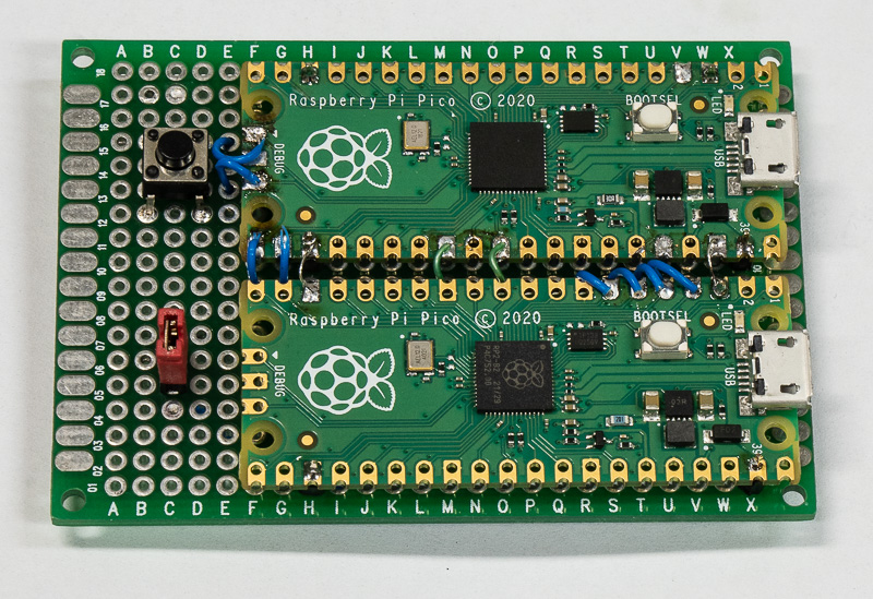
The above image adds two things. One is a reset button (that resets the board up top, which I call the "target" board). With a reset button, if you have new code, you just hold down both reset and bootsel, then release reset and just a bit after you reset bootsel. As long as the bootrom code sees BOOTSEL asserted when it starts up, it will go into USB mass storage mode.
I also added a second Pico with the picoprobe firmware installed. This is connected to the SWD pins on the upper "target" board. It also connects the probe uart to UART0 on the target board via pins 21 and 22. Note that the picoprobe provides both a USB to serial facility as well as a SWD gateway you can use with openocd. And it provides both simultaneously.
I also provide a jumper to connect Vsys from the probe board to the target board. This allows me to connect a cable only to the probe board and use openocd to load and debug code. Or I can ignore the probe board entirely and just connect a USB cable to my target board and will then appreciate my reset button. Or someday I can begin working on code that uses USB on the target board and then I might have both USB cables connected.
Each board uses less than 50 mA of power, so there is no problem powering them both from a single USB cable (rated at 500 mA).
Someday I will mount this little board on a base of some sort so the cable(s) don't drag it off my desktop.
Tom's electronics pages / tom@mmto.org