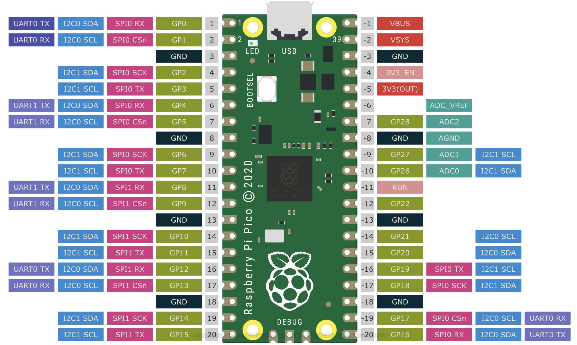
The board has 20 pads on each side and 3 pads on the end for a debug interface.

The "RUN" pin is an active low reset. Provide a button to pull this to ground.
The onboard LED is on GPIO-25.
GPIO-23 controls the SMPS power save pin
GPIO-24 gives high if VBUS (from USB) is present
GPIO-29 gives Vsys/3 via ADC3(which is the 5V supply from USB)
It is possible to power the module from 1.8 to 5 volt supplies, which allows use of Li-ion batteries.
Tom's electronics pages / tom@mmto.org