Hardware Overview
The computer hardware for this project consists of the usual VME rack
and power supply and several cards.
The CPU board for this project is a Motorola mvme167 board which
contains a MC68040 chip with 4M of ram. This small amount of
memory is seriously taxed by running WindX user interfaces on
the control computer. Tests have shown that even without the
GUI code running, it is not possible to run the cell control
software on the slower MV68030 based mvme147 board.
In addition to the CPU board, we have an amazingly modest complement
of interface boards, only 2 besides the CPU:
- Greensprings VIPC610 carrier (VME short IO at 0xE000)
- Acromag 9330
16-bit ADC card (VME short IO at 0x0400)
The 4 IP-module slots are used as follows:
- slot A - empty (would be IP-DAC in the test stand)
- slot B - IP-precision 12-bit ADC.
- slot C - IP-digital 48 (mux control, etc.)
- slot D - IP-digital 48 (actuator DACs, etc.)
None of these use interrupts at this time (the acromag driver may be
updated at some point to use interrupts).
Timer interrupts (the timer is on the CPU board) provide a clock tick
at a 1000 Hz rate.
This fast clock is subdivided to activate tasks within the cell
software at appropriate rates, only a few tasks actually run at
1000 Hz.
Starting the Software
The cell computer (mmtcell) is a diskless machine running VxWorks.
When this computer is turned on, it attempts to get a copy of
VxWorks, as well as the cell software over the network from a boot
host (at this time, hacksaw). Once it has booted and started the
cell software, the network is no longer necessary, although it
will be impossible to give commands to raise and lower the mirror
without using the network. When the crate has booted, loaded
the cell software, and started the latter running, it produces
the "bouncing ball" display on the LED's on the front of the VME
computer.
At this point, it will be desirable to start a set of user
interface windows on some computer. This is typically done
on hacksaw by giving the command "vcell all". This command
sends a series of messages to the VME crate instructing it
to start X windows tasks (using the VxWorks hosted X library
"WindX" running in the crate). These GUI tasks display over
the network to some X server (typically hacksaw). These interfaces
are true "legacy code", and we are eager to reimplement them
with Perl/Tk or Ruby/GTK scripts.
Raising the Mirror
Once the crate (mmtcell) is booted up and the user interfaces
are running, use the airon button to turn on the valves that
supply air to the cell. Use the bump button to run a bump test,
and if that goes OK, use the autoraise button to lift the mirror.
Whatever you do, do not use the raise/lower buttons in the upper
left corner of the control window (if you do, no harm done, but
let the raise finish, use lower to set it back down, then use
autoraise instead). Once the lift is done, use the position
window to apply any mirror tilts or position offsets.
Lowering the Mirror
Use the autolower button. People often ask why it takes so
long to lift and lower the mirror. It is all a question of
how fast the stepper motors that extend and retract the hardpoints
can be stepped. We limit the mirror lift to keep the hardpoint
breakaway mechanism engaged throughout the lift or lower.
Stopping the Software
Once the mirror is down, you can power off and/or unplug the
cell crate. Rebooting or unplugging the cell crate while the
mirror is up is to be avoided at all costs. Doing so will
cause the electronics the drop the mirror in an abrupt and
hard to predict fashion.
Panics, Errors, and Limits
The cell software uses the term "panic" for the action it takes
when it finds an unacceptable condition.
Numerous checks are performed constantly by the software while it
is running. Any of these may be viewed as a possible hazard to the
mirror, and will result in what is called a "panic".
Because the software has identified a dangerous condition that it
is unable to correct or control, the action it takes is
to deactivate the air control valves.
This results in as rapid an evacuation of air pressure
as has been deemed safe from the support system, resulting in
an almost immediate dropping of the mirror onto the static supports.
The control window provides a "panic button" which the operator
can use at any time to cause this to happen. A mirror panic is
always a safe option at any time the operator identifies an unsafe
condition, although simply lowering the mirror is the better choice
if conditions permit.
It is a fundamental design concept that a panic is always an acceptable
option, and the software at any time can take evasive action by panicing
the cell. A key example where the only possible option is a panic is
when a actuator control DAC fails in such a way that it is commanding
a maximum force regardless of computer command (we have had two DAC's
fail in this way thus far).
The following limits cause panics or in some cases truncation of
commanded forces to the limit value:
- Actuator X force: +- 400 pounds
- Actuator Y force: +- 450 pounds
- Actuator Z force: +- [0,G00] +- 90 pounds
- Total X force: +- 5000 pounds
- Total Y force: -800 to 22000 pounds
- Total Z force: -800 to 22000 pounds
- Total X moment: +- 160000 inch-pounds
- Total Y moment: +- 40000 inch-pounds
- Total Z moment: +- 40000 inch-pounds
The individual Y force limits are interesting, since we have
50 duals, and the mirror weighs 20900 pounds, when horizon pointing
each must exert 418 pounds to support the mirror, we have an excess
ability of 1600 pounds to respond to disturbances. The total Z and
Y force limits give an excess of 1100 pounds, which is perhaps too
tight. Perhaps even more interesting, consider our 6 square inch
area piston being delivered 100 psi air. It can produce a 600 pound
force, but multiply this by .7071 since it is at a 45 degree angle
and we get 424 pounds; just a bit above what we need. If we supply
120 psi air (and we intend to), we will get 20 percent above what we
expect to need, and a 20-30 percent "headroom" is about what we think
is right.
Outer loop transient testing
This section is pretty out of date, but here it is until we
document some new and improved facilities.
There is a program called xtran that can be run on hacksaw
and which communicates via sockets with the cell computer to do
this testing. One way to invoke it is:
xtran 10 >data
This requests 10 seconds of outer loop data and places it into a file
called data. The outer loop runs at 37 hertz and presently we collect
the transient data at the outer loop rate, so this will be a 370 line
ascii file. A limit of 100 seconds of data is imposed. The file
consists of 12 columns. The first 6 columns are forces and moments in
the order Fx, Fy, Fz, Mx, My, Mz. The last 6 columns are hard point
lvdt readings transformed into sensible
coordinates in the order: X, Y, Z, tilt-X, tilt-Y, tilt-Z.
More interesting is to bump the target value for one of the loops
and look at the transient response. This is done via the command:
xtran 10 2 20. >data
As above, this collects 10 seconds of data (370 points), but 2 new
arguments specify a loop and a bump value. The loop selector (2 in this
case) is a number from 0-5, and the value after is a force increment in
pounds, or a moment increment in inch-pounds. Notice that these are
given as increments to the current loop target, rather than as a new
loop target. The loop selectors are as follows:
- 0 - X force
- 1 - Y force
- 2 - Z force
- 3 - X moment
- 4 - Y moment
- 5 - Z moment
Graphing xtran data
We used to do this with iraf "graph", and you still can if you choose
to do so. We also have (or had) awk scripts to pull columns out of
the file to be fed to a graphing program. The following documents
on way of making graphs, circa 1988 or so:
First to run a command to yank the column of interest out of the file.
There are several scripts named "getfx", "getmy" and the like
that are invoked like this:
getfx data >xfile
Running IRAF and invoking graph are a world of issues unto themselves,
but the following worked pretty well once upon a time:
graph xfile
If you want paper copy invoke the graph command as:
graph xfile dev=stdplot
Don't forget to gflush, (sigh!).
GUI Screen Shots
Here are some screen shots of the GUI that we use to
control the cell software. This ancient and funky GUI is
implemented using WindX (X windows running directly in the
VxWorks computer), but has served us fine for years, here
you go:
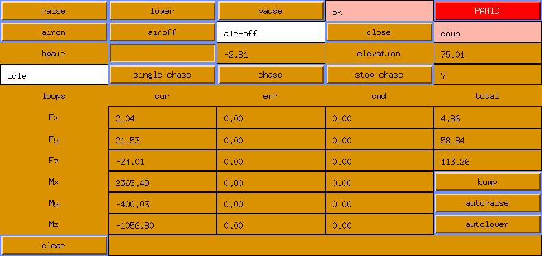
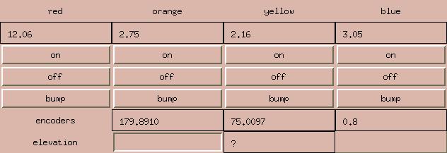
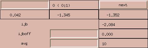
Here is the control window (xcell1)
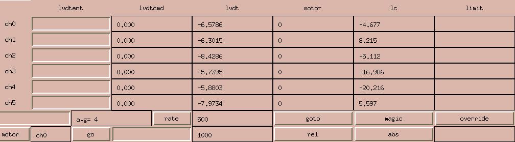
Here is the hardpoint window (xcell0)
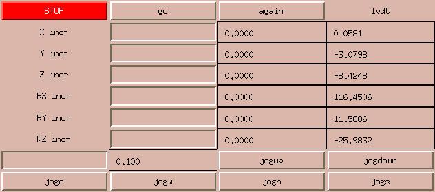
Here is the position window (xcell3)
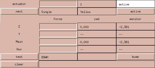
Here is the actuator window (xcell4)
We only use this to diagnose problems
Here is the air window (xcell6)
We almost never use it though.
Here is the thermocouple window (xcell5)
We absolutely NEVER use this one.
Actuator Calibration
A test stand has been built and used to test and calibrate actuators
outside of the cell. This test stand has its own vme chassis and card
complement, and can be run independently of the cell itself. It uses
2 dac channels on an IP-DAC module in slot A of a VIPC610 carrier to
command the actuator. The stand has 6 load cells which allow it to
monitor forces and moments on and around any axis. Additionally,
the load cells on the actuator are monitored as well. All load cells
are monitored by an Acromag 9330 16-bit ADC board.
The test stand is controlled via a serial terminal (nothing else
was provided, so we dug this out of a closet). A more razzle-dazzle
interface may be worked up someday, if we run out of more important
things to do and some appropriate hardware is obtained.
Each actuator is subjected to the following "autocalibration"
procedure. The actuator is bolted to the test stand and connected
to a bottle of pressurized nitrogen at 120psi. The software then
performs the following sequence:
- Set the DAC volts per pound to the nominal values (.01491).
- Disable the integrator.
- Command a force of 0.0 pounds (on both axes).
- Wait 10 seconds.
- Read the test stand values and record them as offsets.
Typically a Z force of 70 pounds will be obtained.
- Enable the integrator.
- Wait 10 seconds.
- Read the test stand values and record them as offsets.
A Z force of nearly 0 pounds ought to be obtained.
- Command actuator 1 to 300 pounds.
- Read the test stand values.
- Calculate P1 = 0.01491 * 300. / Z-stand.
- Calculate PM1 = P1 * actuator load cell / actuator dac.
- Set the dac volts per pound to P1
- Command actuator 1 to 300 pounds.
- ... To be continued ...