Adafruit 32u4 Breakout Pins and Hardware
May 21, 2013
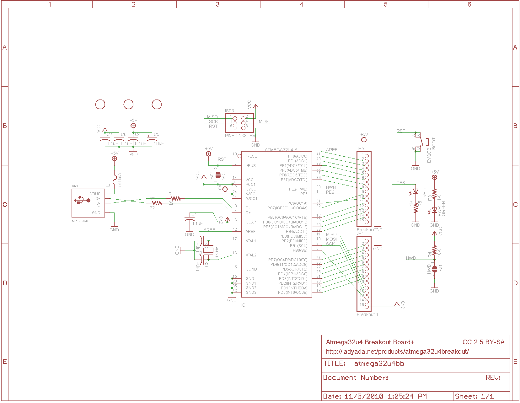
The board has 30 pins, 15 on each side:
Once nice thing I will note right off is that the silkscreen on
the boards labels the pins in correspondence with the Atmel datasheet
rather than some invented fictitious system, which is nice.
We have:
- Port B - all 8 pins
- Port C - C6 and C7
- Port D - all 8 pins
- Port E - E6
- Port F - F0,1 F4,5,6,7
That is 25 pins in all.
The "missing" pins (with the exception of E2)
are signals that Atmel did not carry to legs on the chip.
The mystery then is: what happened to E2?
E2 is connected on the board to what they call "HWB",
which is pulled up via a resistor and offers a
pad to optionally connect it to ground. The idea here is that you
can cut this trace and disable the boot loader. The description on
the website says:
If you ever want to disable the bootloader you can cut the bottom 'HWB' jumper trace.
This will disconnect the 'hardware bootloader' pin,
you can then use the button as a plain reset button.
For the first few runs of this board we set the fuses to still use the bootloader
even with the HWB jumper cut,
if you want to get rid of the bootloader,
please set the fuses to remove the BOOTRST fuse. Sorry!
The other signal on the edge of the board is "A", which is analog ground.
And we have 2 grounds, 5V power and 3.3V power.
The 5V power comes directly from the USB (via a 500 mA fuse).
The 3.3V comes from pin 6 on the ATmega32u4, so don't expect much current.
32u4 hardware notes
Like other 8 bit Atmel AVR controllers, the 32u4 uses several discrete address spaces.
Data and Code address are separate (what is known as a Harvard architecture).
There is also a distinct third address space for EEPROM, which much be accessed
through special instructions.
As near as I can tell, IO ports occupy the first part of the data address space.
- Flash memory (32K) 0 - 7fff
- Processor Registers 0 - 1f (in data space)
- IO ports 20 - 5f
- external ports 60 - ff
- SRAM 100 - aff
- eePROM 0 - 3ff
The datasheet is a 433 page monster (but we aren't complaining).
Here is a sort of table of contents that I prepared before I realized that
it was the crummy PDF viewer now built into firefox that was not showing me
the table of contents built into the document.
- pages 1 - 8 Introduction
- pages 9 - 17 CPU core
- pages 18 - 26 Addressing
- pages 27 - 42 Clock
- pages 43 - 48 Power Management
- pages 49 - 60 Reset
- pages 61 - 64 Interrupts
- pages 65 - 84 IO ports
- pages 85 - 88 external interrupts
- pages 89 - 176 counters and timers.
- pages 177 - 185 SPI
- pages 186 - 222 USART
- pages 223 - 252 TWI (two wire interface)
- pages 252 - 288 USB
- pages 289 - 291 Analog Comparator
- pages 292 - 313 ADC
- pages 314 - 329 JTAG
- pages 330 - 345 Boot Loader
- pages 346 - 377 Device Programming (flash,eeprom,fuses)
- pages 378 - 407 Electrical specs
- pages 408 - 411 ** Register summary
- pages 412 - 414 Instruction summary
- pages 415 - 418 ordering info
- pages 419 - 424 Errata
- pages 425 - 433 Table of Contents
Feedback? Questions?
Drop me a line!
Tom's Computer Info / tom@mmto.org