Inside the unit are two circuit boards. I call these the power board and the logic board.
The power board is connected to line AC, has two triac devices (one for the heater, one for the fan), and a variety of not to complicated circuitry.
The logic board is under the control panel. It has a microcontroller (a PIC16F690), the display, the encoder knob, and the user interface buttons.
The logic board is connected to the power board by a 6 wire cable. If we understand this cable, we can replace the logic board, which is my goal ultimately. The six signals are as follows. The colors are correct for my unit (no telling about yours), and I give the signals in order.
Black - ground
Orange - zero crossings (status)
Red - ready (status)
Yellow - heater command
Blue - +12 from power board
Brown - fan command
And there you have it. Here are some comments on the above.
First an important note. The unit has no real power switch. When it is plugged in, everything is powered up, signals are all active, code in the microcontroller is running, and it is just waiting for the user to push some buttons.
Power. The 12 volts is just adequate to run the existing logic board. Don't think of using it to power something else. It is derived via a series resistor and shunt zener diode to give crude regulator designed for a specific current draw.
The logic board has a regulator circuit based on a TL431 shunt regulator chip that develops +5 from the +12 to run the PIC and other logic circuitry.
The red signal I label "ready" is odd and I really don't see the reason for it. It is derived from the orange zero crossing signal via an RC filter. When I look at it with a scope, I see it always high around 12 volts. I call it "ready", as I don't know what else to call a signal that is always high when the power is on.
The orange signal is sort of a half wave rectified signal with a +12 volt amplitude. It is fed to the base of a transistor on the logic board, which results in a logic level signal that goes low when we are in the positive part of a power cycle and high when we are in the negative part. No doubt the transitions are used to generate the timings on the command signals relative to zero crossings on the AC line.
The command signals have brief (14 microsecond) low going pulses at the appropriate times in each half cycle to trigger the triacs. See my page on "signals" for details. These signals are driven by open collector transistors and serve to sink current and turn on an LED that is part of an optocoupler on the power board.
Interestingly, these include internal resistors. One in series with the base, the other from base to ground.
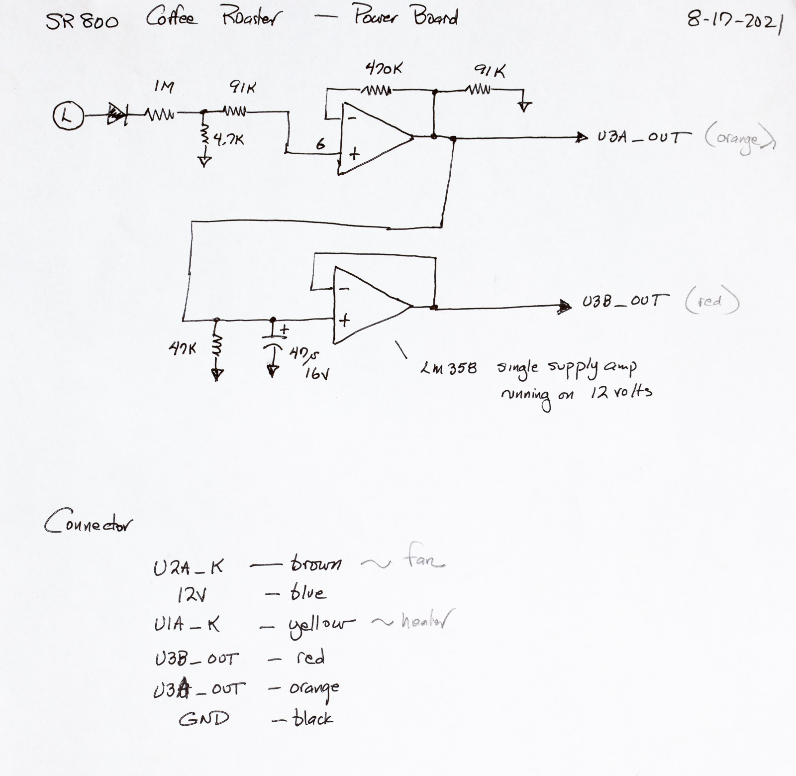
First we have the zero crossing circuit. We get two signals from the dual op amp. I find only the first (U3A_OUT on orange) to be of interest.
Second we have this diagram which shows the most important thing, namely how the logic board sends and receives signals from the power board.

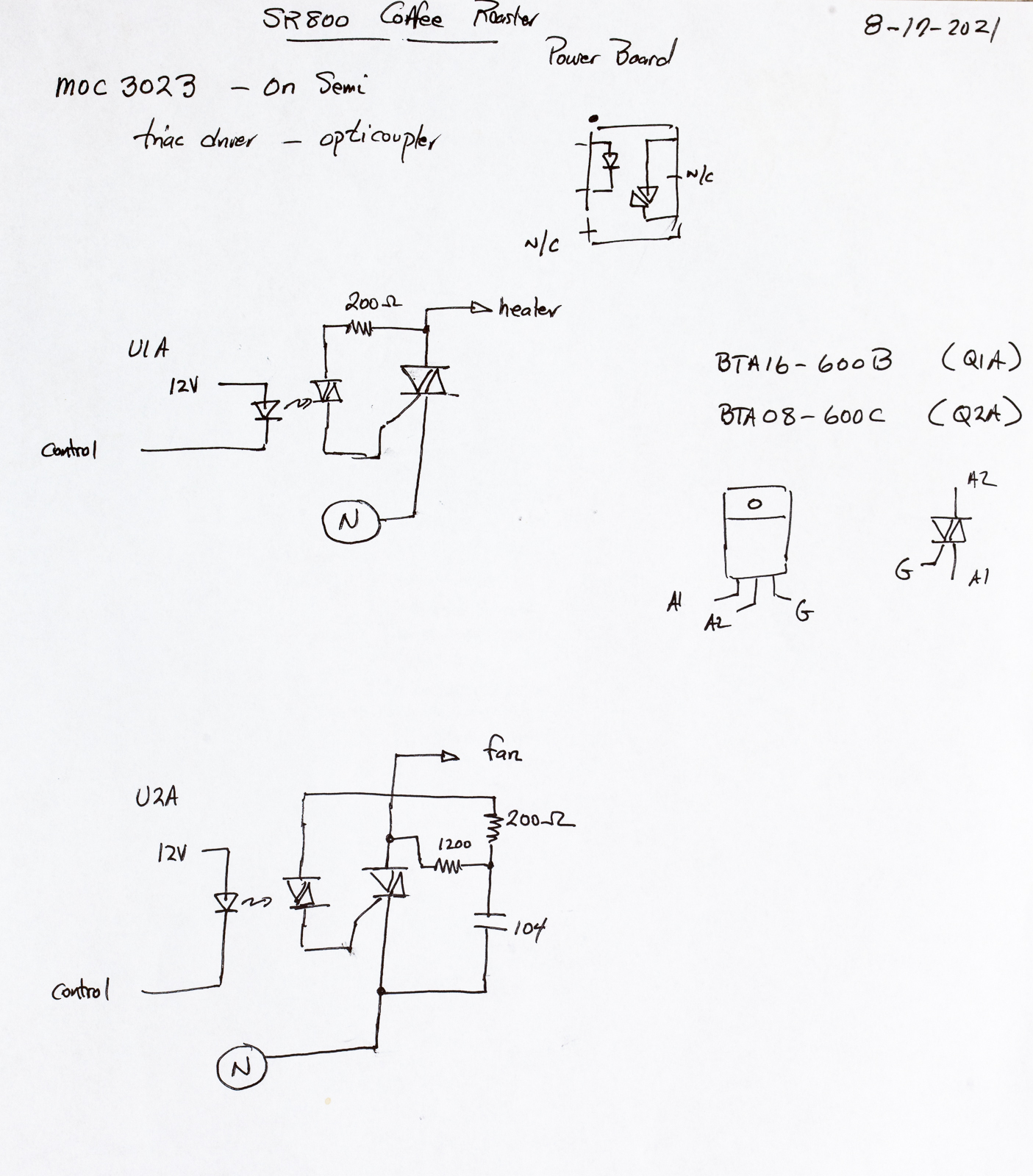
Last we have this, which shows the triac based control of the heater and fan. Really the only thing interesting is that the game is controlled by an optocoupler and you need to provide a pulse (through an all important 1K resistor) to ground the diode to trigger the triac.
And there you have it. Pretty much all you need to know. But if you have questions, feel free to ask.
Tom's coffee pages / tom@mmto.org